Flashlight bodies: heat sinking, wall thickness and O-ring grooves
A flashlight body is a heat path and a seal. How material, wall thickness and fins set LED temperature, and how to specify O-ring grooves and threads that seal.
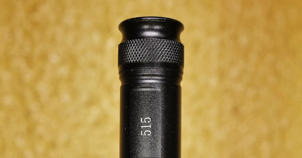
A flashlight body does three jobs at once. It carries the battery, it seals out water and it takes the heat from the LED to the air. Designers usually spend their time on the first job. The second and third decide whether the light survives a rainy night and a ten-minute run on high.
Heat is a path, not a property
An LED turns most of its electrical power into heat, often well over half. That heat must flow from the LED board through a metal pill or the head wall into the body and then into the air or the hand. The material, the cross section and the contact between parts set how well it flows.
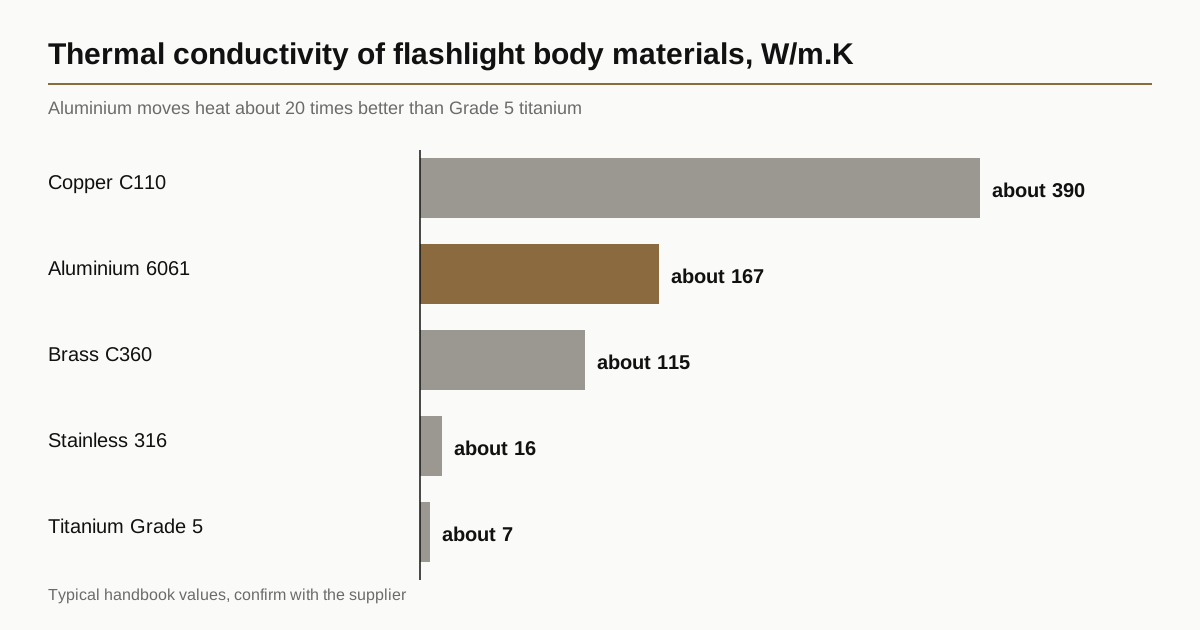
Thermal conductivity differs hugely between materials commonly used for bodies:
| Material | Thermal conductivity W/m·K | Notes for flashlights |
|---|---|---|
| Copper C110 | about 390 | best conduction, heavy, tarnishes |
| Aluminium 6061 | about 167 | standard choice, light, anodizes |
| Brass C360 | about 115 | heavy, warm look |
| Stainless 316 | about 16 | poor conduction |
| Titanium Grade 5 | about 7 | very poor, needs a copper or aluminium core |
Values are typical handbook figures and vary with temper. The point is the ratio. Aluminium moves heat roughly twenty times better than Grade 5 titanium, which is why a titanium light with a powerful LED often uses a copper or aluminium pill inside.
Wall thickness
A thick wall carries more heat. A thin wall saves weight and cost. A typical aluminium body has a wall of 1.5 to 3 mm in the tube and more at the head, where the LED sits. Heavy bodies for high-power lights may have walls over 4 mm and fins.
Points that matter:
- At the head, the wall should be thick enough to carry the heat from the pill to the outer surface and to the cooling fins.
- At the tube, wall thickness sets stiffness and the space for threads and O-ring grooves.
- At threads, a thread cut into a thin wall may leave very little material below the root. Keep thread depth modest.
A thicker wall also helps with the next point, which is machining. Thin tubes chatter and distort when clamped or turned. Ask the shop how it plans to support the part.
Fins and surface area
Fins increase surface area, which helps heat leave the head. Turned fins are common on lights. Typical fin pitch is a few millimetres, depth is a few millimetres and the cut is a grooving operation on a lathe.
- More fins help only if air can reach them. In a pocket or a hand, the hand is the main heat sink.
- Anodize colour matters little for convection but a dark surface radiates a bit better.
- Fin tips are sharp. Break the edges and keep a minimum fin thickness, around 1 mm, so the fins survive a drop.
The thermal joint
A metal-to-metal joint between the LED board and the pill, and between the pill and the head, conducts only where the surfaces touch. Surface flatness and finish matter. Thermal paste or a thin pad fills gaps. The shop should hold the seat flat to a few hundredths of a millimetre and clean it. Do not anodize the contact surface. Mask it or machine after anodizing, because anodize coating is a thermal and electrical insulator.
O-ring grooves
Most flashlights seal with O-rings at the head, the tailcap and sometimes the switch. A well-designed O-ring gland has three parts: the groove, the mating surface and the lead-in that guides the ring into place.
Typical guidance from O-ring handbooks for static seals is:
- Squeeze of about 15 to 30 percent of the O-ring cross section.
- Groove width about 1.25 to 1.5 times the cross section, to leave room for the ring to deform.
- Surface finish on sealing surfaces of about Ra 0.8 µm or better, with no spiral tool marks across the seal.
- Lead-in chamfer of about 15 to 30 degrees at the edge so the ring is not cut during assembly.
- No sharp edge at the groove corners.
For a common 1.78 mm cross-section O-ring, a radial static groove is typically near 2.4 to 2.5 mm wide and 1.3 to 1.4 mm deep, with the mating bore giving the remaining squeeze. Always check the groove against the O-ring maker’s handbook for the exact size and application.
Common mistakes
- Groove on a thread run-out. The ring falls into the thread and is cut. Keep grooves away from the thread.
- Spiral marks on the sealing face. A turned surface with a coarse feed leaves leak paths. Specify a finishing pass.
- Anodize in the groove. Hard anodize has a rough texture. It can help or harm. Test the leak rate on sample parts.
- Wrong O-ring material. Nitrile is common and cheap. Silicone suits wide temperature ranges but is more prone to cuts. Fluoroelastomer suits fuels and heat.
Threads and electrical contact
Many lights use the body threads as part of the electrical path. If the threads are anodized, current cannot pass and the light will not turn on or will flicker. The usual solutions are:
- Mask the threads before anodizing, then leave them bare.
- Machine the anodize off the thread after coating.
- Use a spring and contact plate so the path does not depend on threads.
Threads are usually coarse trapezoidal or square forms, which cope with anodize and dirt better than fine V threads. Lubricate with silicone grease. Flashlight threads, galling and anodize allowance goes through the allowance in detail, and Type II vs Type III anodizing helps with the coating choice.
Testing the seal
There is a published test scheme for flashlights, ANSI/PLATO FL1, which covers water resistance, impact resistance and light output. Water ratings use IP codes defined in IEC 60529. A common approach for makers is to submerge sample lights in water for the stated time and check for moisture. A better test is a pressure decay test on the empty body before assembly, which finds leaks in seconds. Ask what test the shop can offer.
Machining plan
A typical machined aluminium body is bar-fed on a CNC lathe with live tooling, so the bore, threads, grooves and fins are all cut in one setup. Cooling fins and knurling on the outside are turned. Cross holes for the switch are drilled and tapped. Anodizing and masking follow.
What to write in the RFQ
- Material and temper, for example 6061-T6
- Wall thickness at head, tube and threads
- O-ring size, groove width, depth and surface finish
- Thread form, pitch and class, and which threads stay bare
- Fin dimensions, if any
- Anodize type, colour and masked areas
- Leak test or pressure test requirement
Send the drawing with the sealing notes, and the shops in the network will reply within 24 business hours.
For the ratings printed on the pack, see flashlight standards: ANSI/PLATO FL 1 and IP ratings.
See also: flashlight body sizes by cell format, with typical bores for AA, 18350, 18650 and 21700 hosts.
FAQ
Can a titanium flashlight run a bright LED? Yes, with a copper or aluminium pill carrying the heat. The titanium shell alone conducts poorly.
How thick should the tube wall be? For aluminium, 1.5 to 3 mm is common. Thicker walls help with threads and heat but add weight.
Why does my light flicker after anodizing? The thread is anodized and blocks current. Mask or remove the coating on the contact surfaces.
What O-ring should I use? Nitrile is a common default. Check temperature and chemical needs and follow the handbook for the groove.
Can machined fins cause leaks? Not directly. Leaks come from grooves, sealing faces and threads, not from fins.